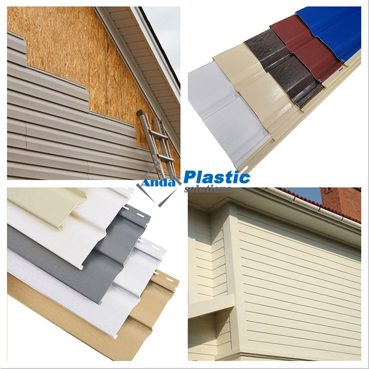
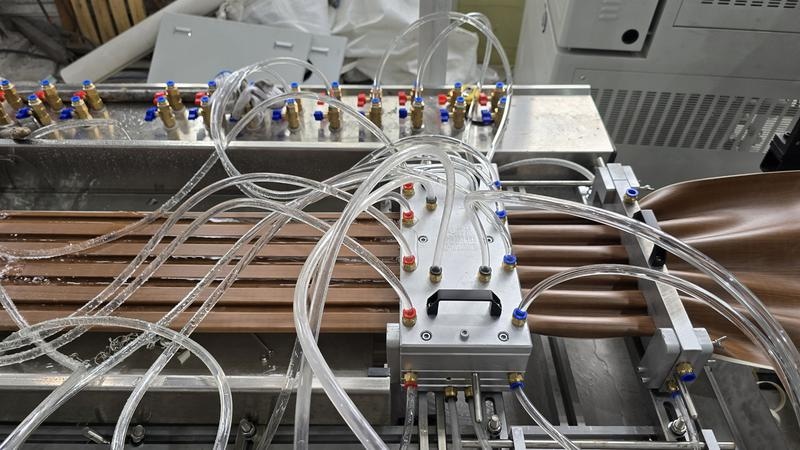
Product Overview: The ANDA PVC Soffit Panel Production Line is designed for the continuous extrusion of rigid PVC soffit panels used beneath roof eaves, porch overhangs and other exterior architectural structures.
The complete production line integrates PVC plasticization, co-extrusion when required, mould forming, vacuum calibration, water cooling, synchronized haul-off, cutting and panel collection.
Three production-line configurations are available for profiles up to 400 mm wide. The available haul-off speed ranges are 1–8 m/min, 1–10 m/min and 1–20 m/min, allowing the line to be selected according to the soffit design, material formulation and required production speed.
Maximum profile width of 400 mm
Three production-line configurations
Haul-off speeds up to 20 m/min
Main extrusion and secondary extrusion systems
Vacuum calibration and controlled water cooling
Synchronized extrusion and haul-off
Solid and vented soffit panel solutions
Optional PVC, ASA or PMMA surface-layer co-extrusion
PVC soffit panels are installed beneath roof edges and overhangs to cover the exposed underside of the roof structure. Different panel designs can provide a clean architectural finish and, where ventilation slots are added, support airflow into the roof cavity.
Producing these thin-wall exterior profiles requires more than simply increasing extrusion speed. Melt flow, mould resistance, vacuum pressure, cooling capacity and haul-off speed must remain balanced throughout production.
The ANDA PVC soffit panel production line is configured around this continuous process.
The main extruder prepares and supplies the structural PVC melt. A secondary extruder can be used where a separate surface layer is required. The combined material passes through the soffit panel mould before entering the calibration and cooling section.
After the dimensions have stabilized, the haul-off unit pulls the panel at a controlled speed. The cutting unit then separates the continuous profile into the required lengths.
The final equipment configuration is selected according to the panel drawing, profile weight, surface structure, material formulation and production target.
PVC Soffit Panels Produced by the Line
With the corresponding mould and auxiliary equipment, the production line can be configured for:
Solid PVC soffit panels
Vented PVC soffit panels
Smooth-surface soffit panels
Embossed soffit panels
Single-colour soffit panels
Co-extruded soffit panels
Interlocking soffit profiles
Custom eave and overhang panels
Different surface widths, edge-locking structures, reinforcing ribs and decorative patterns require corresponding moulds and calibration tooling.
Ventilation holes or slots normally require an additional punching or perforating process. The perforation method should be selected according to the hole pattern, panel thickness and required production speed.
Main Equipment Configuration
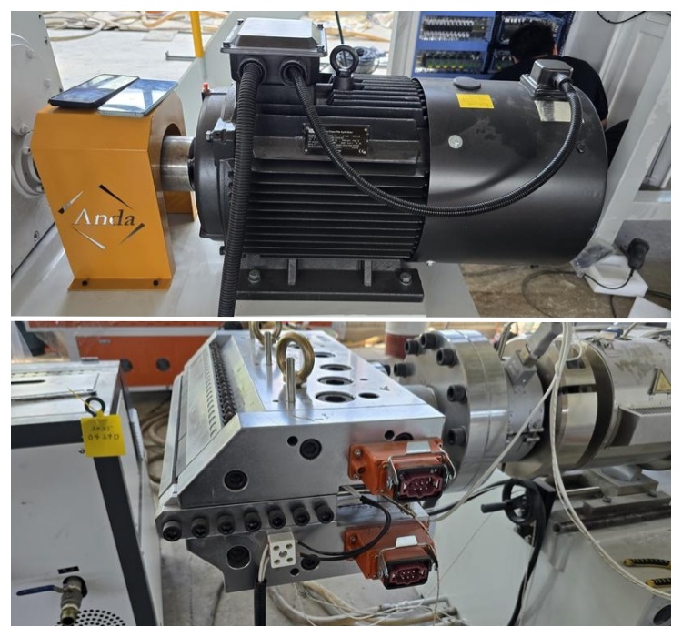
Main PVC Extrusion Unit
The main extruder processes the prepared PVC compound and supplies the structural material for the soffit panel.
The screw and barrel system must provide controlled material conveying, compression and plasticization. Stable melt flow supports consistent mould pressure and wall-thickness distribution.
Important extrusion controls include:
Feeding stability
Barrel temperature
Screw speed
Screw torque
Melt pressure
Residence time
Extrusion output
PVC has a limited processing window. Insufficient heat or shear can cause incomplete plasticization, while excessive temperature or residence time can lead to discoloration and material degradation.
Secondary Extrusion Unit
Each listed production-line configuration includes a secondary extrusion system.
Where a co-extruded surface is required, the secondary unit supplies the surface-layer material to the co-extrusion mould. The main and secondary extruders must operate at a stable ratio to prevent surface-layer variation.
The secondary extrusion system can support surface formulations based on PVC, ASA or PMMA when they are compatible with the selected mould and production process.
The required surface material, layer thickness and bonding conditions must be confirmed through formulation and mould evaluation.
PVC Soffit Panel Mould
The mould determines the main geometry of the finished soffit panel.
It controls:
Overall panel width
Panel thickness
Surface profile
Internal reinforcing ribs
Interlocking edges
Fastening flanges
Co-extruded surface distribution
Balanced flow channels help distribute the PVC melt across the full mould width. The mould design must compensate for differences between thick structural sections and thin decorative sections.
A custom mould is required for each significantly different soffit panel cross-section.
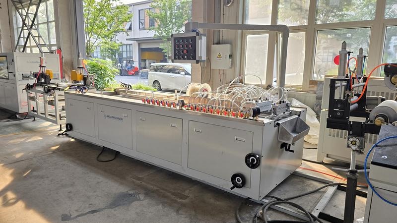
Vacuum Calibration Table
The calibration table receives the hot profile directly from the extrusion mould.
Vacuum calibrators hold the panel surface and edges in position while cooling circuits remove heat. Stable vacuum distribution helps maintain the required cross-section without drawing marks or local deformation.
The calibration table should provide:
Accurate alignment with the mould
Adjustable vacuum pressure
Controlled cooling-water circulation
Independent cooling sections where required
Stable support for wide, thin-wall panels
Convenient calibrator adjustment
Insufficient calibration can cause width variation or poorly formed edges. Excessive vacuum may leave surface marks or increase traction resistance.
Water Cooling System
The cooling system removes heat from the formed profile before haul-off and cutting.
Uniform cooling is particularly important for soffit panels because uneven temperature distribution can produce bending, twisting and surface waves.
Cooling performance is affected by:
Water temperature
Water flow
Cooling-channel design
Calibrator contact
Production speed
Profile wall thickness
Ambient conditions
When line speed increases, the cooling system must remove more heat within the same production distance.
Synchronized Haul-Off Unit
The haul-off unit provides the continuous traction required to move the soffit panel through the production line.
Traction speed and pressure must be adjusted together. Insufficient pressure can cause slipping, while excessive pressure can deform the hollow or thin-wall profile.
Stable haul-off performance supports:
Consistent panel dimensions
Controlled wall thickness
Reduced surface marking
Stable cutting length
Continuous production
Uniform co-extruded layers
The haul-off contact surface should provide sufficient grip without damaging the finished panel.
Optional Ventilation-Hole Processing
Vented soffit panels require accurately positioned holes or slots to provide the intended open area and appearance.
Depending on the panel design, ventilation processing may use:
Online punching
Online slotting
Offline perforating
Custom punching dies
The punching method should be evaluated according to the panel width, thickness, hole arrangement and line speed.
Ventilation equipment is project-specific and should be confirmed before the production-line layout is finalized.
Cutting and Collection System
The cutting unit separates the continuous soffit profile into the required finished length.
Cutting timing must follow the haul-off speed. Guide alignment, blade condition and clamping pressure affect cut quality and dimensional accuracy.
The collection system supports the panel after cutting and helps prevent bending or surface damage.
Technical Specifications
Production-Line Configuration
SJZ65/132-SJZ45/100 + YF400
SJP75/28-SJZ45/100 + YF400
SJP90/32-SJZ55/110 + YF400
Maximum Profile Width
400 mm
400 mm
400 mm
Haul-Off Height
100 mm
100 mm
100 mm
Haul-Off Speed
1–8 m/min
1–10 m/min
1–20 m/min
Main Extrusion System
SJZ65/132
SJP75/28
SJP90/32
Secondary Extrusion System
SJZ45/100
SJZ45/100
SJZ55/110
Downstream Equipment
YF400
YF400
YF400
Suitable Material
Prepared PVC compound
Prepared PVC compound
Prepared PVC compound
Surface-Layer Co-Extrusion
Available when required
Available when required
Available when required
Soffit Mould
Custom-designed
Custom-designed
Custom-designed
FAQ
What does a PVC soffit panel production line produce?
It continuously produces rigid PVC panels used beneath roof eaves, porch overhangs, balconies and similar architectural structures. The finished panel geometry is determined by the extrusion mould and calibration tooling.
What is the maximum soffit panel width?
The three listed production-line configurations support a maximum profile width of 400 mm. The actual panel width must be confirmed through the drawing and mould design.
What is the maximum production speed?
The highest listed haul-off adjustment range is 1–20 m/min for the SJP90/32-SJZ55/110 + YF400 configuration.
The actual stable production speed depends on the panel weight, formulation, mould, calibration efficiency, cooling capacity and quality requirements.
Can the line produce different soffit panel designs?
Yes. Different panel cross-sections can be produced by changing the mould and matching calibration tooling.
The extruder and downstream equipment must have sufficient capacity for the selected panel width, weight and production speed.
Can the line produce vented soffit panels?
Yes, when the line is configured with suitable ventilation-hole processing equipment.
Because hole patterns differ between products, the punching or perforating system must be selected according to the panel drawing and required line speed.
Why does the production line include a secondary extruder?
The secondary extruder can supply a separate surface material for co-extruded soffit panels.
It allows the structural PVC body and surface layer to be processed through the same mould. The materials and extrusion ratio must be confirmed for each product.
Can ASA or PMMA be used for the surface layer?
PVC, ASA or PMMA surface-layer solutions can be evaluated according to the mould and material compatibility.
The finished product’s weathering performance must be verified through formulation-specific testing.
Can one line produce both solid and vented panels?
The same basic extrusion line may support solid and vented designs by changing the mould, calibration tooling and ventilation-processing setup.
The feasibility should be confirmed from the two panel drawings.
How is panel flatness controlled?
Flatness depends on balanced mould flow, correct calibration alignment, stable vacuum pressure, uniform water cooling and synchronized haul-off.
Material formulation and wall-thickness distribution also affect flatness.
Does maximum haul-off speed equal actual production speed?
No. Maximum haul-off speed is the equipment adjustment limit.
Actual production speed is restricted by melt output, profile weight, cooling time, punching requirements and finished-panel quality.
Can the electrical configuration match local power standards?
The required voltage, frequency and phase should be provided before production. The final electrical configuration will be stated in the technical proposal.
What information is required for a quotation?
Please provide the panel drawing, width, thickness, weight, formulation, surface-layer requirement, vent pattern, target output, cutting length and electrical standard.
Heating and Cooling PVC mixer compound machine is widely used to mix PVC powder with some other materials in the industry of PVC pipe, PVC profile, PVC board/sheet, WPC material batching compounding and so on.
Decoration PVC Marble Sheet Making Machine is applied to produce PVC sheet with width of 1220mm and length with 2440mm, thickness mostly from 2.5 to 4mm. The surface of PVC sheet generally treated by hot stamping or lamination, then coated by UV varnish. By switching film with different color. After coating UV glossy varnish, the surface of PVC sheet is more smooth and wearable. It can also produce LVT floor by some adjustment and with related auxiliary machines.
LVT floor production line mainly produces LVT floor with 1200mm wide and 1.5-3mm thick. It has the advantages of high degree of automation, simple operation, stable and reliable production operation and high yield.
PVC door and window profile making machine mainly composed by conical Twin Screw Extruder, Cooling Table, Hauling Machine, Cutting Machine, Stacker. With different moulds, it can produce various UPVC profile, such as: PVC window door profile, PVC wall panel, PVC window sill board, cabinet door board, curtain box, PVC trucking, cable duct, PVC skirting, PVC protection corner and so on. And by changing screw barrel and mould, it can also produce PVC based WPC products, such as: WPC wall panel, WPC window door frame moldings, skirting moldings, WPC door board etc.
The Bamboo Charcoal Wall Panel Production Line is designed for continuous extrusion production of bamboo charcoal decorative wall panels in different profiles, sizes and surface finishes. The complete line integrates a conical twin screw extruder, customized extrusion die, vacuum calibration table, cooling system, haul-off, cutting machine and stacker. Anda Machinery can customize the production line according to the bamboo charcoal material formulation, wall panel profile, dimensions, target output and surface finishing requirements.
The ANDA WPC louver panel production line produces PVC-based louver, fluted, slat and decorative wall panels. It integrates feeding, extrusion, calibration, cooling, haul-off and cutting. Optional hot stamping creates various decorative finishes. Different panel sizes and profiles can be produced by changing the molds. Main Production Capabilities:
Produces WPC louver and fluted wall panels
Supports reference panel widths from 200 to 600 mm
Product Overview: The ANDA PVC Ceiling Panel Extrusion Line is designed for the continuous production of rigid PVC ceiling panels and hollow decorative ceiling profiles.
The complete line integrates PVC plasticization, mould forming, vacuum calibration, water cooling, synchronized haul-off and automatic cutting. Optional hot-stamping or laminating equipment can be added for decorative surface finishing.
Four machine configurations support common panel widths from 200 mm to 600 mm. Reference production capacity ranges from more than 800 m² to 3,300 m² per day, depending on the panel weight, PVC formulation, mould structure and cooling conditions.
UPVC ceiling panel production line is used to produce PVC ceiling tiles with 595x595, 600×600 , 603x603. The surface of PVC ceiling tile can be treated by to hot stamping for different color or patterns to fit various decoration style.
Anda Twin screw Pvc Edge Banding Production Line is used to produce PVC edge band, it's widely used for edge sealing of MDF, HDF, particle board, composite board and so on.
PVC edge band production line with Calender Cooling is used to produce PVC edge band with different width, section shape and thickness. The surface of PVC edge band can be treated by three color printing & coated with glossy oil, or by heat transfer printing.
The PVC Door Board Making Machine is designed to manufacture rigid PVC door boards through a continuous extrusion process. Available in YF700, YF800 and YF900 configurations, it supports maximum board widths of 700 mm, 800 mm and 1000 mm, with production capacity of up to 10,000 kg per day. The machine provides stable extrusion, precise temperature control and flexible configuration options for PVC door board manufacturers.
PVC Water Pipe Making Machine Overview: The PVC Water Pipe Making Machine is designed for continuous production of PVC and UPVC pipes for water supply, agricultural irrigation, well casing, drainage, and other fluid transportation applications.
Wide Pipe Range: Produces PVC/UPVC pipes from 16–800 mm in diameter.
High Output: Available capacities from approximately 150–1300 kg/h.
Complete Production Process: Integrates extrusion, moulding, vacuum calibration, hauling, cutting, stacking, and optional belling.
Flexible Pipe Production: Different pipe diameters and wall thicknesses can be produced by changing suitable tooling.
Stable & Automated Control: Siemens PLC and SSR heating control support centralized operation and stable extrusion.
Water Pipe Applications: Suitable for water supply, agricultural irrigation, well casing, drainage, and fluid transportation pipes.
The PVC Conduit Pipe Making Machine is designed for efficient production of PVC and UPVC electrical conduit pipes for cable protection and wiring applications.
Double Output: Produces two conduit pipes simultaneously for higher efficiency.
Pipe Size:Supports conduit diameters from **16–63 mm**.
High Output: Production capacity of approximately **125–200 kg/h**.
 English